
Solar panel microcracks are one of the most common types of solar cell damage that can affect PV module performance and long-term reliability. Unlike obvious physical damage, microcracks may not be visible during a standard visual inspection.
They are typically identified through EL (Electroluminescence) testing, while IV Curve testing and IR Thermography can help evaluate whether cracks are causing electrical or thermal abnormalities.
For solar module manufacturers, distributors, installers, and project buyers, understanding how to identify and investigate microcracks is important for quality control, transportation management, installation, and long-term module performance.
This guide explains the common causes of solar panel microcracks and provides a practical framework for RCA (Root Cause Analysis).
1. What Are Solar Panel Microcracks?
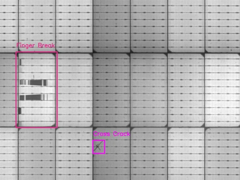
Solar cell microcracks are small fractures that occur within crystalline silicon solar cells. Some cracks may initially have little or no measurable effect on module output, while others can electrically isolate parts of a cell and reduce its effective active area.
Microcracks can occur during:
-
Wafer and cell manufacturing
-
Cell stringing and interconnection
-
Module lamination
-
Packaging and transportation
-
Storage and handling
-
Installation
-
Long-term operation
A key point is that the presence of a crack does not automatically mean that a solar module has failed.
The actual impact depends on factors such as crack location, crack length, electrical isolation, cell current, module design, and whether the crack continues to develop.
Therefore, microcrack assessment should combine physical inspection with electrical and thermal testing rather than relying on visual appearance alone.
2. Common Causes of Solar Cell Microcracks
2.1 Manufacturing and Cell Processing
Manufacturing is one possible stage where cracks can be introduced.
Potential contributing factors include:
-
Wafer or cell mechanical defects
-
Excessive mechanical stress during handling
-
Cell soldering and interconnection stress
-
Improper stringing parameters
-
Thermal stress during processing
-
Lamination process conditions
-
Material and process variation
During module manufacturing, solar cells are subjected to mechanical and thermal loads. If the process parameters are not properly controlled, existing defects may develop into visible cracks.
For RCA, it is important to examine production records, cell batches, EL images, stringing processes, and lamination parameters rather than assigning the cause based only on crack shape.
2.2 Transportation and Handling
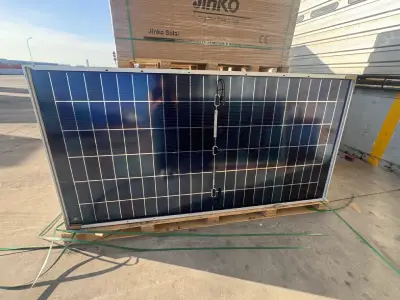
Solar modules can experience mechanical stress during loading, unloading, transportation, and storage.
Potential factors include:
-
Excessive vibration
-
Impact during handling
-
Improper stacking
-
Packaging damage
-
Forklift or handling incidents
-
Uneven loading conditions
However, a network-like or cross-shaped crack pattern alone is not sufficient to prove that transportation caused the damage.
A more reliable investigation compares the module condition at different stages:
Factory EL → Arrival EL → Post-Installation EL → Operational EL
If a crack is absent in the factory EL image but appears in an inspection after transportation, transportation or handling becomes an important investigation area.
3. Installation-Related Cell Cracking
Solar modules can also be damaged during installation.

Common risk factors include:
-
Incorrect clamping
-
Excessive mounting pressure
-
Improper support
-
Walking or standing on modules
-
Uneven mounting structures
-
Excessive mechanical stress during installation
-
Incorrect handling of modules
Clamp positions and mounting requirements should always follow the specific manufacturer’s installation manual. A fixed distance should not be treated as a universal rule because different module designs have different mechanical requirements.
Installation-related RCA should therefore consider:
-
Module installation records
-
Mounting structure design
-
Clamp type and position
-
Installation procedures
-
EL inspection before and after installation
This evidence can help distinguish installation-related damage from defects that already existed before installation.
4. How to Detect Solar Panel Microcracks
Visual inspection alone cannot reliably identify all microcracks.
Three commonly used inspection methods are EL, IV Curve testing, and IR Thermography.
4.1 EL (Electroluminescence) Testing
EL testing is one of the most useful methods for identifying cracks and other internal cell abnormalities.
An EL image can reveal:
-
Microcracks
-
Cell fractures
-
Inactive cell areas
-
Broken fingers
-
Interconnection abnormalities
-
Localized dark regions
EL inspection is particularly useful for quality control because it allows the condition of individual cells to be examined.
For RCA, comparing EL images from different stages can be more informative than examining a single image.
4.2 IV Curve Testing
An IV Curve measures the electrical characteristics of a PV module.
Important parameters include:
-
Voc — Open-Circuit Voltage
-
Isc — Short-Circuit Current
-
Pmax — Maximum Power
-
Fill Factor (FF)
Microcracks may affect electrical performance when they cause part of a cell to become electrically isolated.
However, an abnormal IV Curve is not unique to microcracks. Other issues, such as mismatch, shading, bypass diode problems, connection defects, or degradation, can also affect IV characteristics.
Therefore, IV testing should be combined with EL and other inspection methods when investigating suspected cell cracking.
4.3 IR Thermography
IR Thermography can help identify abnormal temperature patterns during module operation.
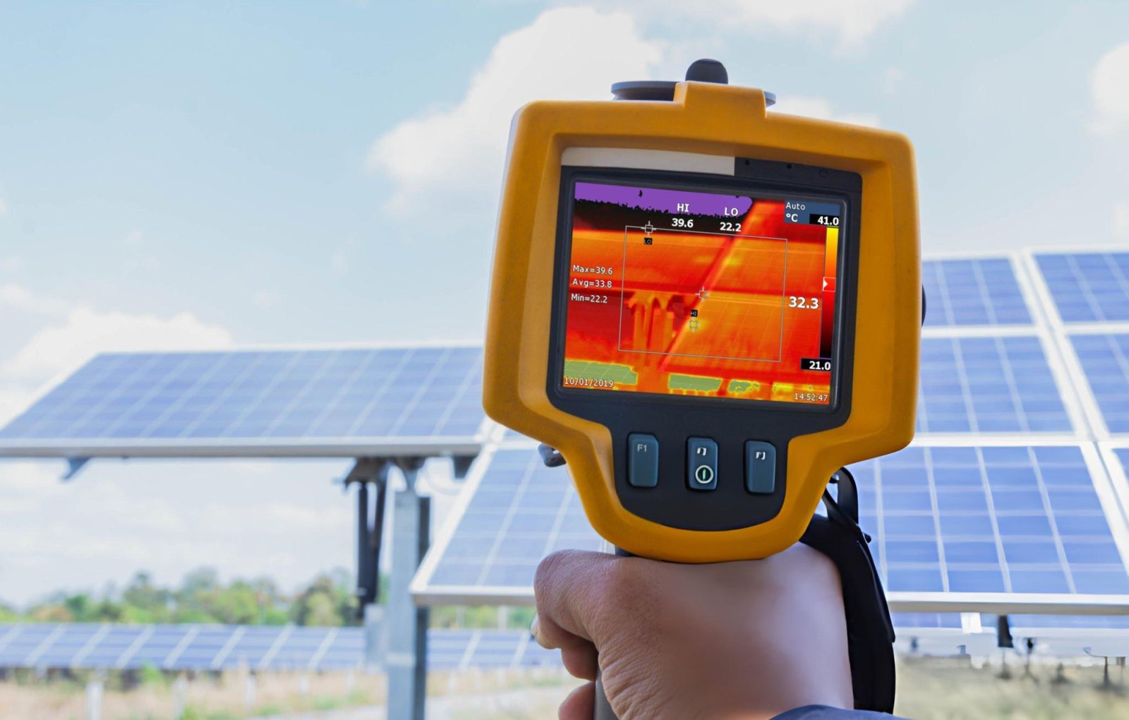
Potential thermal abnormalities may be associated with:
-
Hot spots
-
Cell mismatch
-
Electrical connection problems
-
Bypass diode issues
-
Localized resistance
However, a microcrack does not automatically result in a hot spot.
Thermal abnormalities should therefore be investigated together with EL images, IV data, operating conditions, and module electrical characteristics.
5. Do Microcracks Cause Hot Spots or Power Loss?
Not every microcrack causes immediate power loss.
The electrical impact depends on whether the crack electrically isolates part of a solar cell and how the affected area interacts with the module’s electrical circuit.
Possible consequences include:
-
Reduced active cell area
-
Lower current output
-
Increased electrical mismatch
-
Localized heating
-
Hot spot formation
-
Reduced Pmax
-
Long-term reliability risks
The severity of a crack should therefore be evaluated based on its electrical impact, not simply its appearance.
A useful assessment combines:
EL + IV Curve + IR Thermography + Visual Inspection
For example, a crack visible in an EL image with no measurable electrical abnormality may require a different response from a crack associated with significant power loss or localized heating.
There is also no single universal temperature difference that can be used to define every hot spot. Thermal interpretation depends on module design, operating conditions, irradiance, ambient temperature, and inspection method.
6. Microcracks During Long-Term Operation
Some cracks may exist without causing immediate performance problems.
However, environmental and mechanical stresses can contribute to the development or propagation of existing defects over time.
Relevant factors may include:
-
Thermal expansion and contraction
-
Wind loading
-
Snow loading
-
Mechanical vibration
-
Humidity
-
Repeated temperature changes
-
Installation stress
Thermal-Mechanical Cycling is particularly relevant when evaluating long-term module reliability.
It is important to distinguish between:
-
When a crack was formed
-
When a crack was first detected
-
Whether an existing crack has propagated
-
Whether the crack has caused measurable electrical degradation
For example, a crack discovered several years after installation does not necessarily mean that it was created several years earlier.
Historical EL records, IV measurements, inspection reports, environmental conditions, and maintenance records can help establish a more reliable timeline.
7. How to Assess the Severity of Solar Cell Cracks
A practical assessment should consider more than crack length or appearance.
Key questions include:
(1) Is the crack electrically significant?
Determine whether part of the cell has become electrically isolated.
(2) Is there measurable power loss?
Compare current IV results with baseline or reference measurements where available.
(3) Is there localized heating?
Use IR Thermography to identify potential thermal abnormalities.
(4) Is the crack propagating?
Compare EL images from different inspection stages whenever historical data is available.
(5) Does the condition meet the relevant acceptance or warranty criteria?
The final assessment should refer to the applicable manufacturer’s specifications, inspection criteria, contractual requirements, and warranty conditions.
This approach is more reliable than classifying a module as defective solely because a crack appears in an EL image.
8. A Practical RCA (Root Cause Analysis) Process
When microcracks are discovered, a structured RCA process can help identify the most likely contributing factors.
Step 1: Preserve Evidence
Collect:
-
Module serial numbers
-
EL images
-
IV test results
-
IR Thermography images
-
Visual inspection photos
-
Packaging condition
-
Transportation records
-
Installation records
Step 2: Establish the Timeline
Determine when the crack was first observed.
Where available, compare:
Factory → Transportation → Installation → Operation
Step 3: Analyze Crack Characteristics
Examine:
-
Crack location
-
Crack direction
-
Crack pattern
-
Affected cells
-
Electrical isolation
-
Relationship with busbars and fingers
Crack morphology can help identify investigation priorities, but it should not be treated as definitive proof of the root cause.
Step 4: Identify Candidate Causes
Possible areas include:
-
Cell manufacturing
-
Stringing
-
Lamination
-
Packaging
-
Transportation
-
Storage
-
Installation
-
Operating conditions
Step 5: Verify the Cause
Use available evidence to test each candidate cause.
The goal is to establish an evidence chain:
Observation → Testing → Timeline → Candidate Cause → Verification → Root Cause → Corrective Action
This is the fundamental principle of effective RCA.
9. How to Reduce the Risk of Solar Panel Microcracks
For buyers and project developers, preventive quality control is often more effective than investigating damage after installation.
Before purchasing solar modules, consider checking:
-
Manufacturer and module specifications
-
Cell technology
-
Manufacturing quality controls
-
EL inspection procedures
-
Packaging standards
-
Transportation arrangements
-
Installation requirements
-
Product warranty
-
Quality inspection records
For larger projects, buyers may also consider conducting pre-shipment inspections and requesting appropriate quality documentation.
Proper handling throughout the supply chain is important because module quality depends not only on cell technology but also on manufacturing, packaging, transportation, storage, and installation.
10. What Should Buyers Check Before Purchasing Solar Modules?
For B2B buyers, microcrack resistance should be considered as part of a broader solar module quality assessment.
When evaluating a supplier, consider:
Product Quality
Check module technology, power rating, dimensions, electrical characteristics, and applicable certifications.
Manufacturing Quality
Understand how the supplier controls cell handling, stringing, lamination, EL inspection, and final quality control.
Packaging and Transportation
Confirm that modules are properly packaged and handled throughout transportation.
Technical Documentation
Request relevant datasheets, installation manuals, warranty information, and inspection documentation.
Supplier Capability
Evaluate product availability, communication, quality control, delivery capability, and after-sales support according to your project requirements.
A reliable solar module supply chain should provide not only competitive pricing but also consistent product quality and appropriate technical support.
Conclusion
Solar panel microcracks are a complex quality issue that can originate or develop at different stages of the PV module lifecycle.
The most reliable way to investigate them is not to rely on crack appearance alone, but to combine:
EL (Electroluminescence) + IV Curve + IR Thermography + Visual Inspection + Timeline Evidence
An effective RCA (Root Cause Analysis) should determine:
-
When the crack appeared
-
What mechanism caused or contributed to it
-
Whether it has caused measurable electrical or thermal impact
For solar module buyers, understanding these factors can help improve quality control and reduce potential risks during transportation, installation, and long-term operation.
Looking for Reliable Solar Modules for Your Project?
Microcrack resistance is only one part of overall solar module quality. Cell technology, module design, manufacturing quality, packaging, transportation, and installation conditions can all affect long-term module performance.
If you are sourcing Jinko, JA Solar, LONGi, Trina, or Tongwei solar modules for commercial, utility-scale, or distribution projects, our team can help you check available models, technical specifications, power ranges, and wholesale supply options based on your project requirements.
Need a reliable solar panel supplier?
Contact our team to discuss your requirements and request product information or a wholesale quotation.
Request a Quote → Contact Us